


Jelly4 MU3L2K7M(AGYYO) 2K USB3.0 Line Scan Industrial Camera
Introduction
Jelly4 series USB 3.0 Line scan industrial cameras are especially well suited for applications that need both high speeds and high image quality. We offer high-performance line scan cameras with resolutions of 2048 (2K) and 4096 (4K) pixels. Monochrome for 2K and 4K, color versions for 2K are available.
Features
1. Mirco USB3.0 High-speed interface, Bandwidth is 5Gb/s, plug and play, no need external power supply;
2. Adopt Awaiba CMOS line scan camera sensor;
3. With FPGA 32MB built-in hardware frame buffer, make sure no frame lost, support more cameras work together;
4. Support GPIO opto-isolated external trigger, line frequency capture, external trigger delay setting does not affect the acquisition frame rate;
5. Provide completed API for users’ secondary development, support VC, VB and other development language;
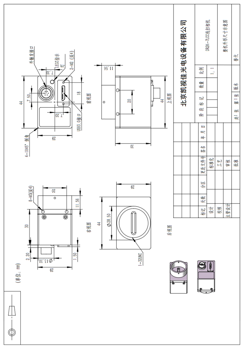
6. Precision aluminum alloy shell, small size 29×44×30mm, weight 63g.
7. Support C-mount interface and customize lens interface.
Applications
The line scan cameras are frequently used in printing machinery to inspect printed images. Surface and web inspection; Regardless of whether working with semi-conductors, paper, plastics or raw leather, line scan cameras are helpful tools for identifying flaws directly within the production process.
Another common use is for postal sorting or reading out barcodes, QR codes, lines of text (OCR) and other codes. This ensures that packages and letters will reach the right recipient in a timely manner.
Specification
Model | MU3L2K7M(AGYYO) | MU3L2K7C(AGYYO) | MU3L4K3M(AGYYO) |
Color/Mono | Mono | Color | Mono |
Sensor Type | CMOS | CMOS | CMOS |
Sensor Model | DR-2K-7 | DR-2K-7 | DR-4K-3.5 |
Shutter | Global | Global | Global |
Sensor Size | 14.3mm | 14.3mm | 14.3mm |
Pixel Size | 7.0×7.0μm | 7.0×7.0μm | 3.5×3.5μm |
Resolution | 2K | 2K | 4K |
Resolution | 2048x1 | 2048x2 | 4096x1 |
Horizontal Frequency | 80MHz | 80MHz | 40MHz |
Pixel Depth | 8 bit | 8 bit | 8 bit |
Min Exp time | 2μs | 2μs | 1μs |
Frame Buffer Joint Capacity | 7398 lines | 7398 lines | 3699 lines |
Interface | USB3.0 | USB3.0 | USB3.0 |
Image Output Format | Raw8/Mono8 | Raw8/Bayer24/32 | Raw8/Mono8 |
Synchronous Control | Internal trigger/soft trigger/external trigger/fixed frame rate trigger | ||
Exposure | Auto / Manual | ||
WorkingTemperature | 0°C~60°C | ||
Storage Temperature | -30°C~70°C | ||
Lens port | C-mount | ||
Image Output | Micro USB3.0, Bandwidth5Gb/s | ||
Power Supply | USB3.0 Power Supply, 900mA@5V | ||
Frame Buffer | 32M Bit | ||
Input/Output | Opto-isolated GPIO, 1 channel external trigger input, 1 channel flash output, 1 channel 5V power supply input / output | ||
Main Function | Image display, image capture (bmp,jpg,tiff), video capture(compressor is optional) | ||
Operation System | SupportWindows XP/7/8/10 32&64 bit Operation System (Linux and Android Operation System custom development) | ||
SDK | SupportVC, VB, C#, DELPHI developing language, support LABVIEW, OPENCV, HALCON, MIL Software | ||
Camera Dimension | 29mm(height)×44mm( width)×30mm(length) | ||
Camera Weight | 63g(High-precision CNC aluminum alloy shell) | ||
Accessories | Color cameras come with IR cut filter(mono camera does not have filter), 3m-5m USB cable with fix screws, 6-pin Hirose GPIO connector, 1 CD with software and SDK. | ||
Spectral Response Curve
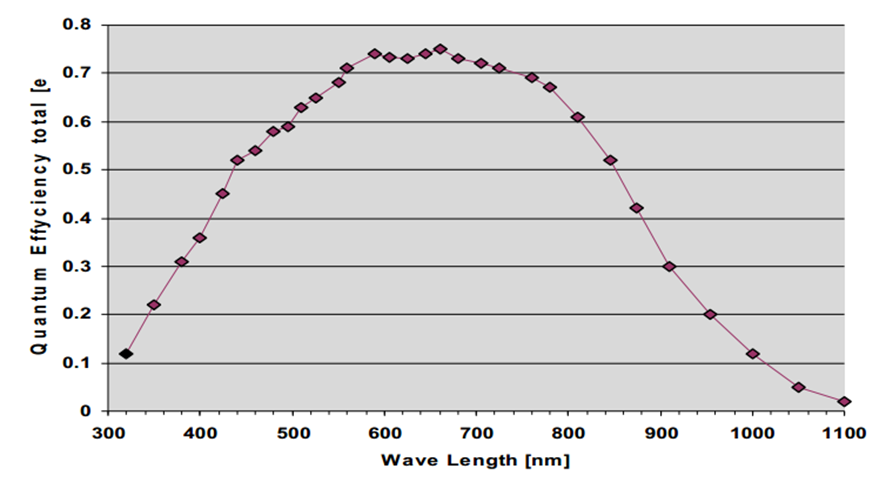
Mono Line Scan Camera (for 2K & 4K)
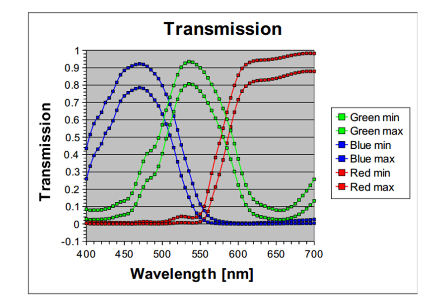
Color Line Scan Camera (for 2K)
Dimension
Unit: mm
GPIO External Trigger interface introduction
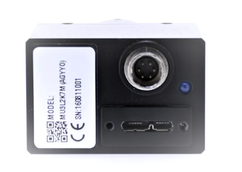
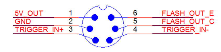
Trigger Serial No | 1 | 2 | 3 | 4 | 5 | 6 |
Cable Color | Red | Black | Yellow | White | Gray | Brown |
Function Symbol | 5V_IN | GND | TRIGGER_IN+ | TRIGGER_IN- | FLASH_OUT_C | FLASH_OUT_E |
Function Definition | Power Supply Input Interface | GPIO Input Interface | GPIO Output Interface | |||
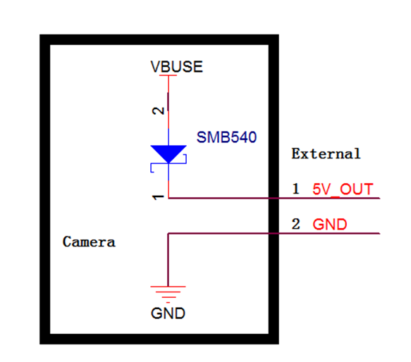
Power Supply Input Interface
The camera is powered by USB3.0 Bus Power, the power supply of USB3.0 standard should be 5V@900mA. In actual applications, sometimes the host is not insufficient for power supply, or because the USB cable is too long, or because of anti-interference requirements, users can use “5V_IN” interface of GPIO to provide power supply for the camera. To ensure stable work of the camera, power requires DC + 5V, Min. = + 4.5V, Max. = + 5.5V; the drive current>1A.
GPIO Input Interface
Regarding the TLP 281 parameters, please refer to instructions manual.
When using “TRIGGER_IN +” as trigger source, the trigger electrical level range is +0V- + 5V. If the trigger source electrical level is out of this range, an external current limiting resistor should be connected to make the optocoupler works around the typical current 10mA, otherwise the optocoupler will have risk of burning.
Limiting resistor is calculated as follows:
R = 100 x ( Vin – 0.7 ) – R0
Vin is Trigger source electrical level
R0 is The camera's internal series resistor 200 Ohm
R is the required external series resistor.