


Jelly3 MU3S40M/C USB3.0 Industrial Digital Camera (Sony IMX287 Sensor)
Introduction
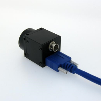
Jelly3 series USB 3.0 industrial digital cameras adopt the latest USB3.0 technology, the speed is much faster than USB2.0 digital cameras, the resolution ranges from 1.2MP to 14.0MP. These cameras have high sensitivity, high dynamic range, hardware frame buffer and high-speed features. Jelly3 series digital cameras can be widely used in machine vision and a variety of image acquisition areas.
Features
8. Support C-mount interface and customize lens interface.
Applications
Jelly3 series USB3.0 industrial cameras are mainly designed for machine vision and various high speed image acquisition areas. They can be used for Gel imaging, License image capture, Medical diagnosis, Microscopy imaging, Notes image capture, Industrial production line image capture, Fingerprint & palmprint image capture, Desktop image, High speed vehicle license plate capture, Outdoor Monitoring, iris capture and etc..
Specification
Model | MU3S40M/C (SGYYO) | MU3S210M/C (SRYYO) | MU3S230M/C (SGYYO) | MU3S231M/C (SGYYO) | MU3S321M/C (SGYYO) | MU3S500M/C (SGYYO) | MU3S640M/C (SRYYO) | MU3S1200M/C (SRYYO) |
Color/Mono | Mono/color | Mono/color | Mono/color | Mono/color | Mono/color | Mono/color | Mono/color | Mono/color |
Sensor Type | CMOS | CMOS | CMOS | CMOS | CMOS | CMOS | CMOS | CMOS |
Sensor Model | Sony IMX287 | SonyIMX290 | Sony IMX174 | Sony IMX249 | Sony IMX265 | Sony IMX264 | Sony IMX178 | Sony IMX226 |
Shutter | Global | Rolling | Global | Global | Global | Global | Rolling | Rolling |
Sensor Size | 1/2.9inch | 1/2.8inch | 1/1.2inch | 1/1.2 inch | 1/1.8 inch | 2/3 inch | 1/1.8 inch | 1/1.7inch |
Pixel Size | 6.3×6.3μm | 2.9×2.9um | 5.86×5.86μm | 5.86×5.86μm | 3.45×3.45um | 3.45×3.45um | 2.4×2.4um | 1.85×1.85um |
MaxResolution | 728x544 | 1944 × 1096 | 1936 × 1216 | 1936 × 1216 | 2048x1536 | 2464× 2056 | 3096× 2080 | 4072× 3046 |
Frame Rate | 328fps | 60fps | 80fps | 40fps | 60fps | 35fps | 30fps | 14fps |
PointFrequency | 96MHz | 96MHz | 96MHz | 96MHz | 96MHz | 96MHz | 96MHz | 96MHz |
ADC Accuracy | 12 bit | 12 bit | 12 bit | 12 bit | 12 bit | 12 bit | 12 bit | 12 bit |
SNR | 47dB | 50dB | 45dB | 45.2dB | 40dB | 40dB | 50dB | 45dB |
Dynamic Range | 74dB | 75dB | 73dB | 72dB | 70dB | 70dB | 70dB | 70dB |
Scan Mode | Progressive Scan | |||||||
Image Output | Micro USB3.0, Bandwidth5Gb/s | |||||||
Power Supply | USB3.0 Power Supply, 300~500mA@5V | |||||||
Frame Buffer | 32M Bit | |||||||
Input/Output | Opto-isolated GPIO, 1 channel external trigger input, 1 channel flash output, 1 channel 5V power supply input / output | |||||||
Main Function | Image display, image capture (bmp, jpg, tiff), video capture(compressor is optional) | |||||||
ProgrammableControl | Preview and capture AOI, SKIP/Binning mode, Contrast, Brightness, Saturation, Gamma, Gain, Exposure, Bad pixel remove, Focus Evaluation, User-defined serial Number(0-255), Hardware LUT(lookup table), Hardware CCM (Color Correction) | |||||||
White Balance | Auto / Manual | |||||||
Exposure | Auto / Manual | |||||||
Image Format | Support 8bit, 24bit, 32bit Image Preview and Capture, Save as “Jpeg”, “Bmp”, “Tiff” format | |||||||
Driver Support | ActiveX, Twain, DirectShow, VFW | |||||||
Operation System | SupportWindows XP/7/8/10 32&64 bit Operation System (Linux and Android Operation System custom development) | |||||||
SDK | SupportVC, VB, C#, DELPHI developing language, support LABVIEW, OPENCV, HALCON, MIL Software | |||||||
Lens Port | C-mount(CS/M12 is optional) | |||||||
WorkingTemperature | 0°C~60°C | |||||||
Storage Temperature | -30°C~70°C | |||||||
Camera Dimension | 29mm(height)×29mm( width)×30mm(length) | |||||||
Camera Weight | 45g(High-precision CNC aluminum alloy shell) | |||||||
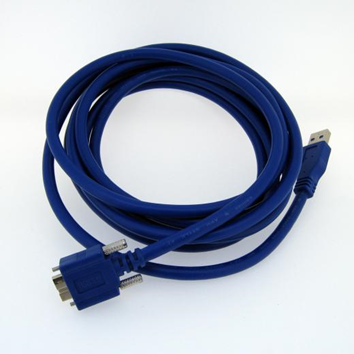
Accessories | Color cameras come with IR cut filter(mono camera does not have filter), 3m USB cable with fix screws, 6-pin Hirose GPIO connector, 1 CD with software and SDK. | |||||||
(2) Cameras with other Sensors
Model | MU3C120M/C (MGYYO) | MU3E130M/C (EGYYO) | MU3I130M/C (IGYYO) | MU3E200M/C (EGYYO) | MU3C500M/C (MRYYO) | MU3C1400M/C (MRYYO) |
Color/Mono | Mono/Color | Mono/Color | Mono/Color | Mono/Color | Mono/Color | Mono/Color |
Sensor Type | CMOS | CMOS | CMOS | CMOS | CMOS | CMOS |
Sensor Model | Aptina AR0134 | E2V EV76C560 | ISG1307 | E2V EV76C570 | Aptina MT9P031 | Aptina MT9F002 |
Shutter | Global | Global | Global | Global | Rolling | Rolling |
Sensor Size | 1/3 inch | 1/1.8 inch | 1/2 inch | 1/1.8 inch | 1/2.5 inch | 1/2.3 inch |
Pixel Size | 3.75×3.75μm | 5.3×5.3μm | 4.8×4.8μm | 4.5×4.5μm | 2.2×2.2um | 1.4×1.4um |
Max Resolution | 1280× 960 | 1280 × 1024 | 1280 × 1024 | 1600 × 1200 | 2592 × 1944 | 4608 × 3288 |
Frame Rate | 60fps | 60fps | 150fps | 60fps | 14fps | 12fps |
Point Frequency | 96MHz | 96MHz | 96MHz | 96MHz | 96MHz | 96MHz |
ADC Accuracy | 12 bit | 10 bit | 10 bit | 10 bit | 12 bit | 12 bit |
SNR | 38dB | 41dB | 41dB | 39dB | 38.1dB | 36.5dB |
Dynamic Range | 64dB | 62dB | 60dB | 52dB | 70.1dB | 65.3dB |
Scan Mode | Progressive Scan | |||||
Image Output | Micro USB3.0, Bandwidth 5Gb/s | |||||
Power Supply | USB3.0 Power Supply, 300~500mA@5V | |||||
Frame Buffer | 32M Bit | |||||
Input/Output | Opto-isolated GPIO, 1 channel external trigger input, 1 channel flash output, 1 channel 5V power supply input / output | |||||
Main Function | Image display, image capture (bmp, jpg, tiff), video capture(compressor is optional) | |||||
Programmable Control | Preview and capture AOI, SKIP/Binning mode, Contrast, Brightness, Saturation, Gamma, Gain, Exposure, Bad pixel remove, Focus Evaluation, User-defined serial Number(0-255), Hardware LUT(lookup table), Hardware CCM (Color Correction) | |||||
White Balance | Auto / Manual | |||||
Exposure | Auto / Manual | |||||
Image Format | Support 8bit, 24bit, 32bit Image Preview and Capture, Save as “Jpeg”, “Bmp”, “Tiff” format | |||||
Driver Support | ActiveX, Twain, DirectShow, VFW | |||||
Operation System | SupportWindows XP/7/8/10 32&64 bit Operation System (Linux and Android Operation System custom development) | |||||
SDK | SupportVC, VB, C#, DELPHI developing language, support LABVIEW, OPENCV, HALCON, MIL Software | |||||
Lens Port | C-mount | |||||
Working Temperature | 0°C~60°C | |||||
Storage Temperature | -30°C~70°C | |||||
Camera Dimension | 29mm(height)×29mm( width)×30mm(length) | |||||
Camera Weight | 45g(High-precision CNC aluminum alloy shell) | |||||
Accessories | Color cameras come with IR cut filter(mono camera does not have filter), 3m USB cable with fix screws, 6-pin Hirose GPIO connector, 1 CD with software and SDK. | |||||
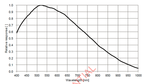
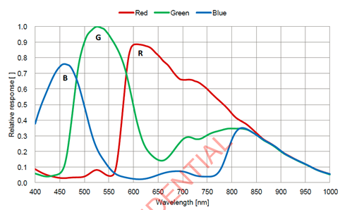
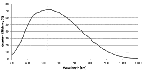
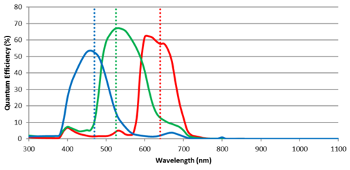
Spectral Response Curve
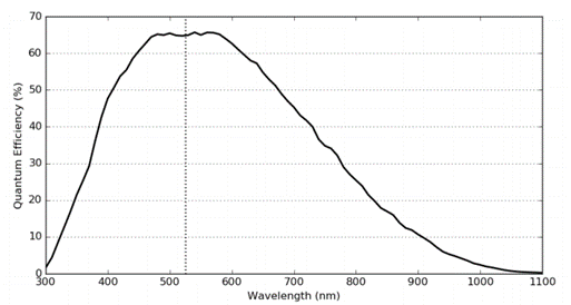
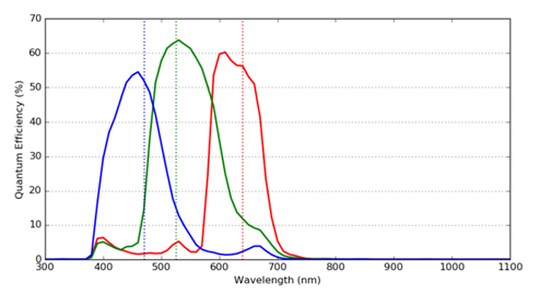
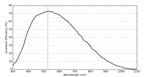
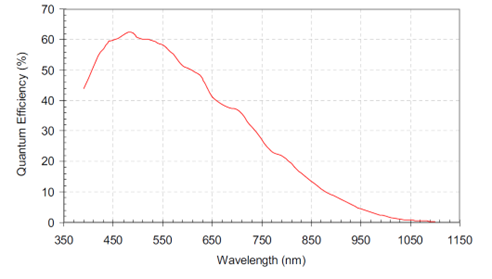
MU3S40M(SGYYO) MU3S40C(SGYYO)
MU3S230/231M(SGYYO) MU3S230/231C(SGYYO)
MU3S321M(SGYYO) MU3S321C(SGYYO)
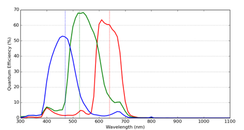
MU3S500M(SGYYO) MU3S500C(SGYYO)
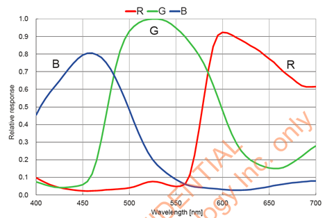
MU3S640C(SGYYO)
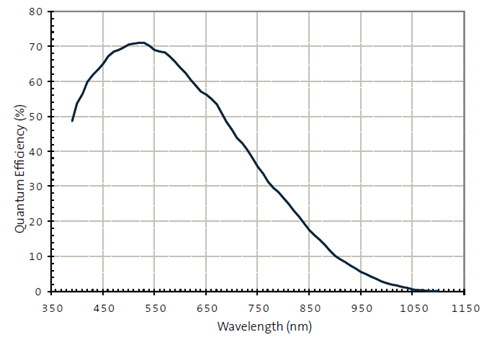
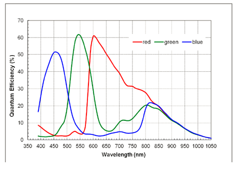
MU3C120M(MGYYO) MU3C120C(MGYYO)
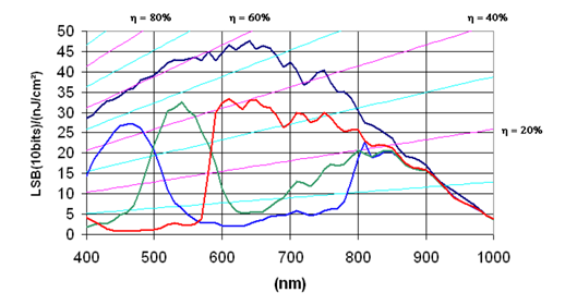
MU3E130M/C(EGYYO)
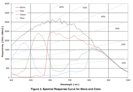
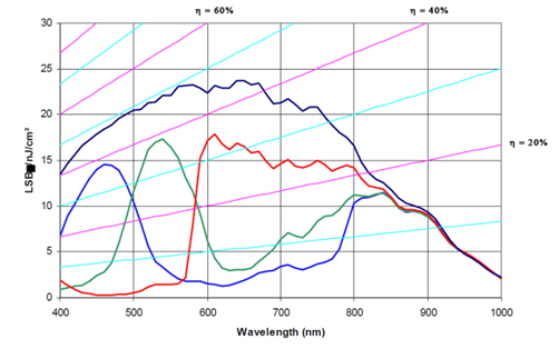
MU3I130M/C(IGYYO) MU3E200M/C (EGYYO)
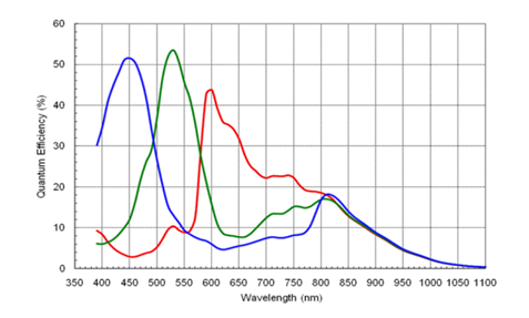
MU3C500M(MRYYO) MU3C500C(MRYYO)
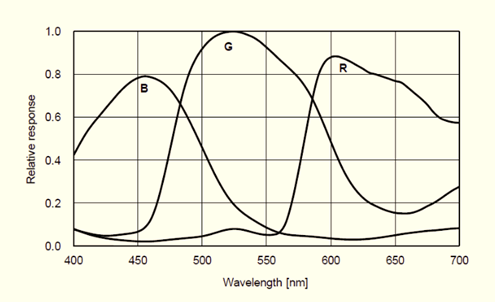
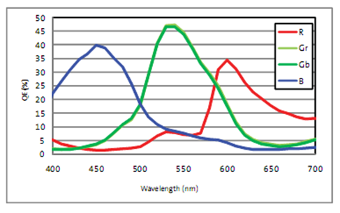
MU3S1200C(MRYYO) MU3C1400C(MRYYO)
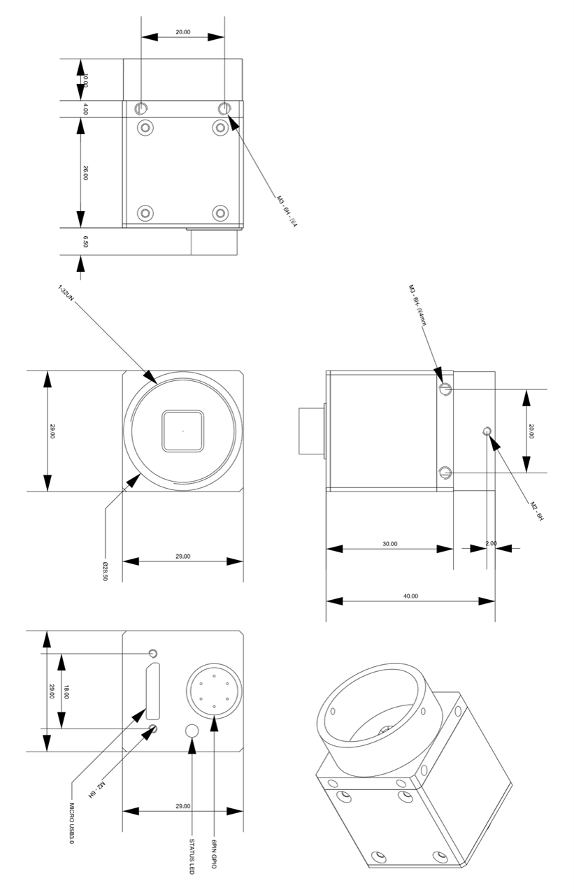
Dimension
Unit: mm
GPIO External Trigger interface introduction
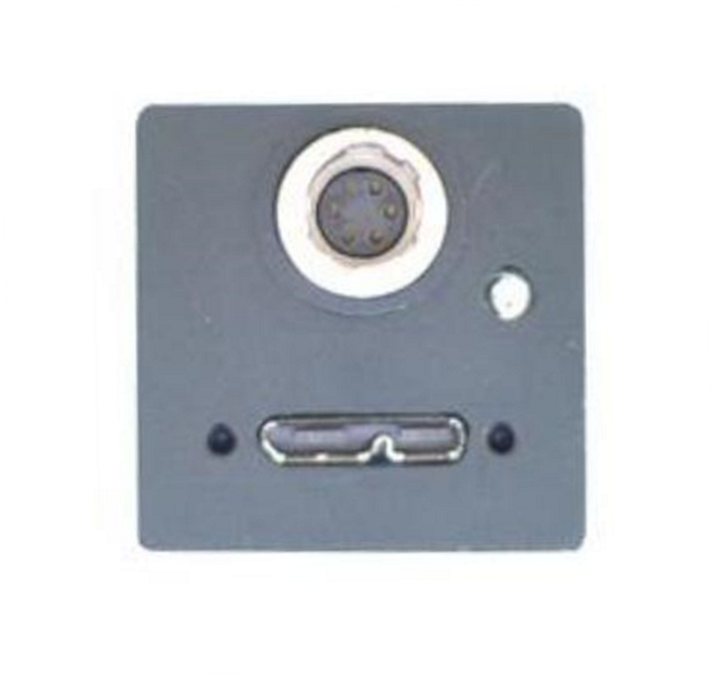
Trigger Serial No | 1 | 2 | 3 | 4 | 5 | 6 |
Cable Color | Red | Black | Yellow | White | Gray | Brown |
Function Symbol | 5V_IN | GND | TRIGGER_IN+ | TRIGGER_IN- | FLASH_OUT_C | FLASH_OUT_E |
Function Definition | Power Supply Input Interface | GPIO Input Interface | GPIO Output Interface | |||
Power Supply Input Interface
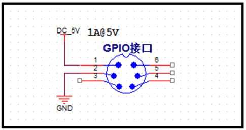
The camera is powered by USB3.0 Bus Power, the power supply of USB3.0 standard should be 5V@900mA. In actual applications, sometimes the host is not insufficient for power supply, or because the USB cable is too long, or because of anti-interference requirements, users can use “5V_IN” interface of GPIO to provide power supply for the camera. To ensure stable work of the camera, power requires DC + 5V, Min. = + 4.5V, Max. = + 5.5V; the drive current>1A.
GPIO Input Interface
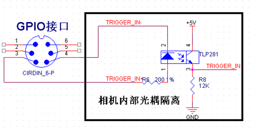
The following figure is the schematic diagram of GPIO input, the input signal has been insulated by opto-coupler TLP281. 200 ohm resistor is in series connection inside the camera. GPIO input interface is generally used for external trigger input signal synchronization acquisition for multi-camera, It also can be used as an external signal acquisition, please refer to the instructions in SDK (software development Kit) for detailed applications.
Regarding the TLP 281 parameters, please refer to instructions manual.
1. The camera's internal optocoupler VCC = 5V, If IF = 16mA, then the external trigger input Rising edge Delay is 2us, Falling edge Delay is 40us;
2. When using “TRIGGER_IN +” as trigger source, the trigger electrical level range is +3V- + 6V.
3. If the trigger source electrical level is lower then 3V, will lead to a trigger signal loss;
4. If the trigger source electrical level is out of this range, an external current limiting resistor should be connected to make the optocoupler works around the typical current 16mA, otherwise the optocoupler will have risk of burning. If the trigger source voltage of 12V, the need for external resistors in series about 1K, if the trigger source voltage of 24V, the need for external resistors in series about 2.2K,
Limiting resistor is calculated as follows:
R = 100 x ( Vin – 0.7 ) – R0
Vin is Trigger source electrical level
R0 is The camera's internal series resistor 200 Ohm
GPIO Output Interface
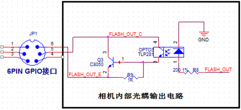
The figure below is the schematic diagram of GPIO output interface, the output signal has been isolated through the optocoupler TLP281, coupled with an NPN audion to magnify drive capability; GPIO interface is generally used to output camera flash light signals, users also can output signal through SDK.
1. GPIO work as a normal IO output.
The following figure shows the ordinary connection when output interface work as normal IO output, the user needs to provide external power supply and pull-up or pull-down resistors.
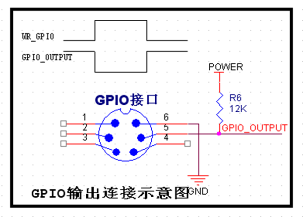
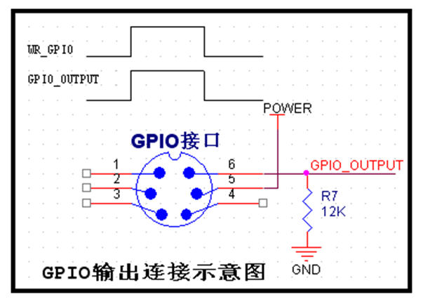
In the figure, “POWER” is the power supply for the user, “WR_GPIO” is the output electrical level signal which is set by the user in SDK. “GPIO_OUTPUT” is the output signal, please note that the output electrical level of the 2 connections is just the opposite.
2. GPIO output to drive external load.
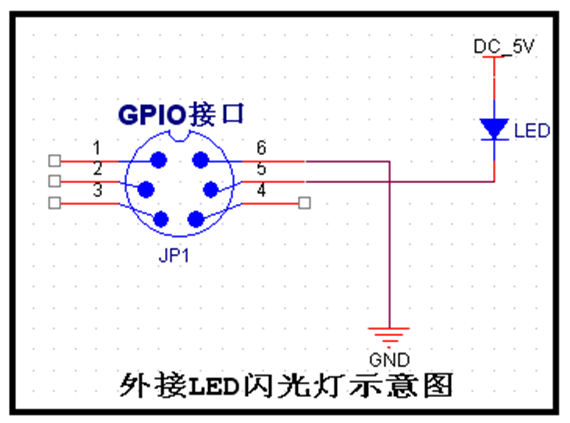
GPIO output interface is an open-drain output, it has certain drive capability to directly drive a small power device, as below figure, it is connected to 5V LED indicating light or low power flash lights.
3. GPIO output interface connected with flash light controller.
The flash trigger interfaces of flash light controller are generally divided into the switch trigger and electrical level trigger two kinds; wire connection diagram is as follows:
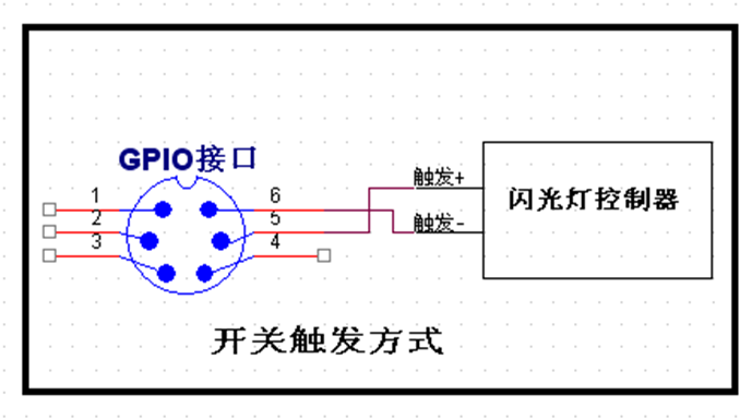
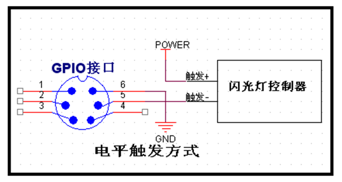
In the figure, “POWER” and “GND” are external power supply for the user, the electrical level should meet the interface requirements of flash light controller.